In the first installment of this two-part series [link], we offered an in-depth, theory-based look at COMP Cam’s new Low Shock Technology (LST) cam lobe design. If you haven’t read that piece yet, some of what we discuss here may be easier to understand with that as a foundation, so take the time to go through that first by clicking here.
This dyno test was designed to look at a number of components. While the focus will be on the LST cam, we also wanted to look at Comp’s new BSR shaft rocker system and the new two-piece adjustable length XD-A pushrods.
The Old Mule
With a good idea of the LST concept and the pieces we will be testing, we rolled out one of our Gen-III LS engines as a testbed. This engine started life as a 24x 6.0L iron-block truck engine. Into which we stuffed a Scat 4.00-inch stroker crank, a set of Scat I-beam 6.100-inch rods, and a set of MAHLE 4.010-inch forged pistons. This engine was originally built back when COMP first created its LRR series of rectangle-port-head-derived line of hydraulic roller camshafts. Our baseline cam for this test is the 281LRR with specs you can find in the accompanying cam specs box.
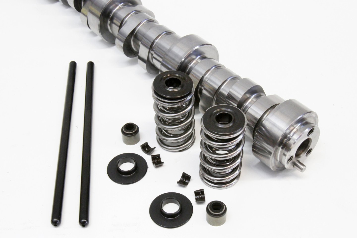
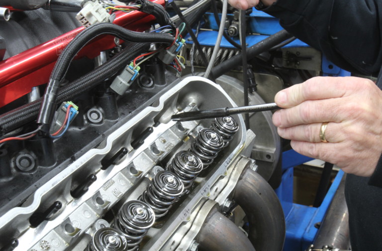
Comp’s new Low Shock Technology cam lobe is the object of our testing. We chose the cam kit which uses all the components shown here including the dual springs, retainers, locks, and pushrods. There is also a master kit that includes lifters.
The short-block was originally fitted with a set of LS3-style rectangle port heads, but we since have converted to a set of smaller, cathedral port Trick Flow Specialties heads with a 225cc intake port volume. These heads, and the accompanying FAST LSXr intake, offer excellent velocity and port flow. We don’t want to get too distracted by this, but these heads and intake made a ton more torque and the same peak horsepower as the rectangle-port heads fitted with a single plane carbureted intake manifold did.
We used this new combination as our starting point to evaluate the Low Shock Technology camshaft. The idea was simple. The Stage-1 LST cam’s specs compared almost exactly to the LRR cam in our 404ci engine, so the comparison would allow us to evaluate if the LST lobe offers any advantages. Looking at the cam specs chart, you can see by comparing the intake lobe duration at 0.050-inch, the new LST cam is exactly the same at 231 degrees.
Camshaft Comparison
281LRR HR-113
| Advertised Duration | Duration at 050″ | Lift | LSA | |
| Intake | 280 | 231 | 0.617 | 113 |
| Exhaust | 296 | 247 | 0.624 |
LST Stage 1
| Advertised Duration | Duration at 050″ | Lift | LSA | |
| Intake | 286 | 231 | 0.614 | 111.5 |
| Exhaust | 293 | 244 | 0.606 |
Note that while the advertised duration is six degrees longer on the LST intake lobe, the duration at 0.050 is the same as the baseline camshaft. This reinforces the concept that the LST’s initial opening rate is slower, applying this 6 degrees of duration to more gently open the valve.
The New Hotness
However, looking at the advertised duration numbers, clearly, there’s a difference. The new LST cam uses a longer, softer ramp, which adds six degrees of duration below .050-inch of valve lift. This difference is described by a term called “hydraulic intensity,” which defines the number of degrees of duration between the advertised opening point of the lobe and the 0.050-inch spec. In this case, the lower the number, the harsher the opening.
The older LRR cam uses 49 degrees to go from the seat to .050-inch of lift, while the LST intake lobe uses 55 degrees to accomplish the same task. As mentioned in the Part I story, the goal of Low Shock Technology was to not abuse the valvespring by slamming the valve open too quickly. These duration numbers support that end goal extremely well.
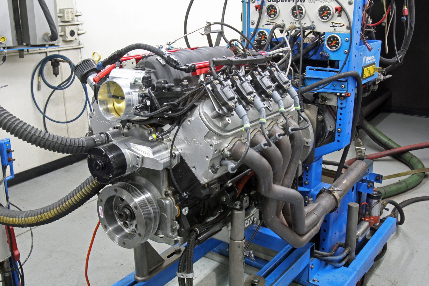
We bolted our 404ci iron block LS motor on Westech’s dyno. Equipped with a Scat rotating assembly with MAHLE 10.0:1 pistons, the headers are a set of Westech’s 1-7/8-inch primary tube pipes. The top end of our 404ci LS test engine consisted of a set of TFS 225cc cathedral port heads, a FAST LSXr intake fed by a 102mm Big Mouth throttle body, all controlled by a Holley HP ECU.
You will also notice that the exhaust duration of the new cam is slightly shorter — both at .050 and in the advertised numbers. This would tend to indicate that the LST cam would not be expected to carry the power out to a higher engine speed. The valve lift numbers did not change appreciably, but the lobe separation angle (LSA) also changed with the LST cam, pulling it in from the LRR cam’s 113-degree separation number to 111.5 degrees.
Tightening the LSA generally opens and closes the intake valve earlier, which tends to enhance torque in the middle while often limiting the peak horsepower number. COMP’s Valvetrain Engineering Group Manager Billy Godbold told us that the LSA number moves around for this family of camshaft lobes to ensure that these cams will always have sufficient piston-to-valve clearance for each application. As such, both the LSA and intake centerline specs will vary based on the application.
While this test was about lobe design, we fell victim to timing of another sort on a more global scale. Our dyno date stuck us in the middle of California’s shelter-in-place decree, but Westech’s Steve Brule wanted to continue, so you will see that all our dyno testing was accomplished with great care taken to keep everybody safe, using masks and gloves. Sometime in the future, readers may wonder why we were wearing face masks — but for now, the requirement was important enough to follow.
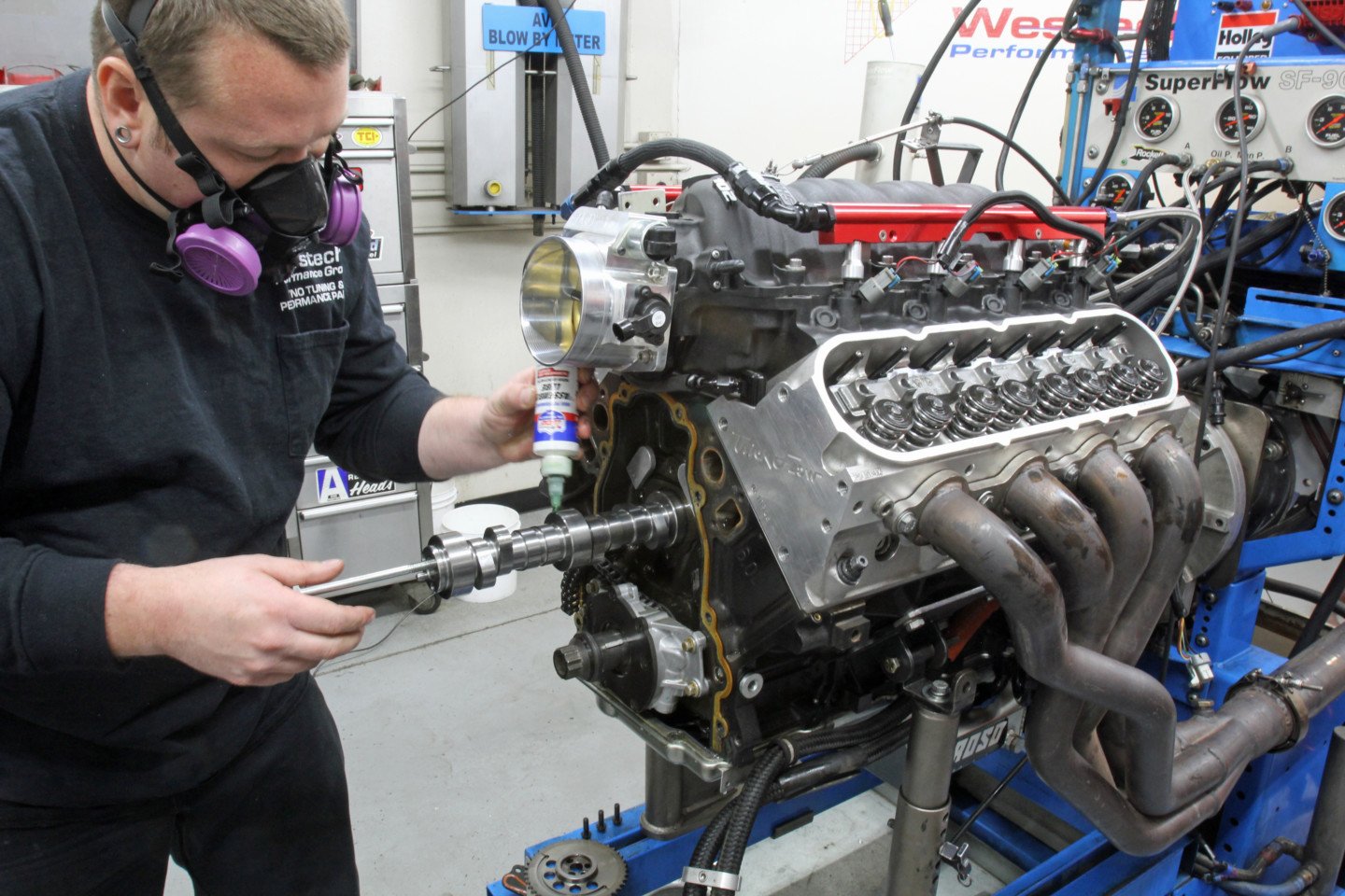
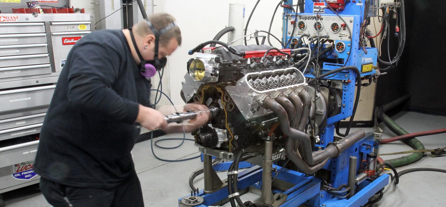
After the baseline runs, it was time for the new LST cam. Goldie has already removed the baseline cam and is installing the new LST cam with Lucas lube. We re-used the original lifters which made the cam swap relatively easy.
Setting The Mark
The baseline power runs went smoothly, controlled by our Holley HP ECU and wiring harness hooked to 65 lb/hr injectors. Once optimized for spark and fuel, our 404ci LS made a decent accounting of itself with 554 lb-ft of torque at 4,600rpm and peak power of 560 at 5,800rpm. The 404 also made excellent torque right off the bottom of the curve with 475 lb-ft at 3,200rpm.
With the baseline established, Westech’s Troy Goldie helped us remove the LRR cam and install the LST version, maintaining the same intake centerline. The LST is designed to use a set of COMP’s dual valvesprings as part of the valvetrain upgrade, so we also exchanged the existing TFS dual spring for the COMP versions while retaining the original pushrod length.
This was an oversight on our part. The LST kit includes a set of 7.450-inch length pushrods while our original set measured 7.400-inch. We should have used the longer pushrods, but in our haste to swap all the parts, the longer pushrods were overlooked.
With everything buttoned back up, Brule pulled the handle on the dyno. The new cam did require some very slight air-fuel ratio tweaking but we made no changes to the ignition timing on the Holley HP ECU. Comparing the power numbers, even though the LST cam offered near-identical duration and lift specs, the new cam delivered an honest 11 horsepower gain at the same RPM as peak power from the previous cam, but extended the horsepower peak from 5,800 rpm to 6,100 rpm.
Since we didn’t spin the baseline test past 6,000, we don’t have any power numbers to compare to, but the peak improved from the baseline 560 to a new top number of 576 horsepower which is a gain of 16 horsepower. With the actual duration and lift being very similar, this immediately begs the question, “why did the power improve?” We think that the enhanced stability from the LST lobe profile offers the ability to open and close the intake valve more accurately and this would certainly contribute to increasing power.
Another variable is the slightly tighter lobe separation angle. Looking at the entire curve, you can see that the LST did lose some torque at the lowest RPM point. The drop in torque is 5 lb-ft at 3,200 but by 3,600 rpm the power is the same and begins to increase slightly all the way to horsepower peak, so the loss was minimal.
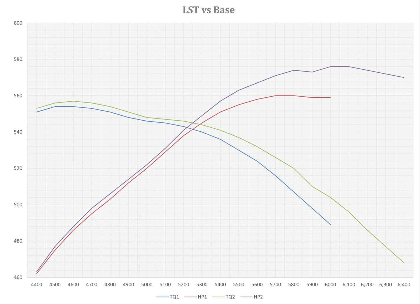
Here, we’ve expanded the top end of the LST cam test to reveal how well the low shock technology performs. From 4,400 to 6,400 you can clearly see the power increase.
Getting the Shaft Isn’t Always Bad
Next, we wanted to take a look at COMP’s Max-Lift BSR shaft rocker system. This test was really easy because all we had to do was clean the two assemblies, lube them, and bolt them in place. The shaft system uses stock GM rockers, replacing the individual roller bearings with bushings and a large diameter common shaft. It bolts directly in place of the original rockers with no modifications.
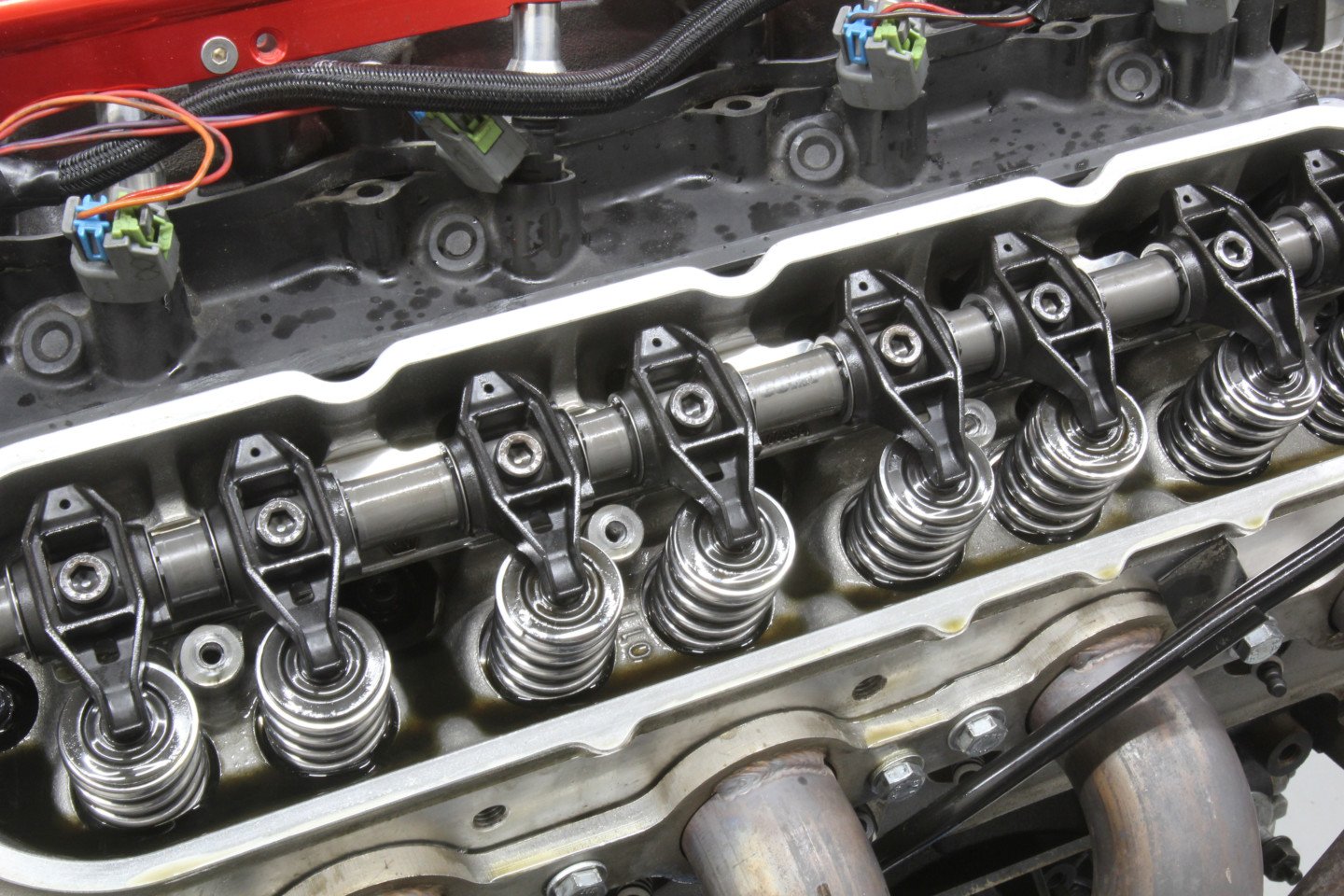
With the cam test complete, we removed the individual rockers and replaced them with the COMP BSR shaft rocker package. This was a simple R&R procedure, leaving the same pushrods in place.
The BSR system is intended for much higher RPM use than we subjected it to here. If we look at the bottom of the curve, we can see that at the start of the test at 3,400 our 404ci LS lost 6 lb-ft but at the top of the RPM curve, the shaft begins to pay off with improved stability by neutralizing deflection and improving power from 572 to 575 hp.
If we had used a longer duration cam to spin this engine up to a power peak of 7,000rpm or higher, the improvements in power would have been even better. We asked Comp’s Billy Godbold to comment on these results and he told us that with less deflection, the cam will essentially appear “bigger” (more duration) at low engine speeds which would account for the minor loss of torque and also why it made more power at the peak.
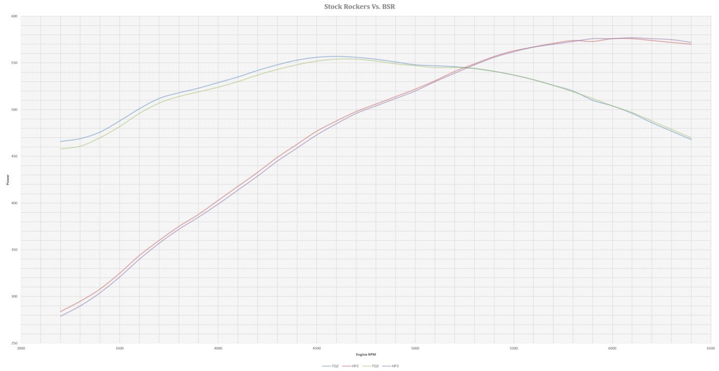
The additional stiffness of the BSR rocker system gave us some unexpected results. Without the deflection of the stock rocker system, the camshaft acted “bigger” than before, resulting in a shifting of the powerband.
Adjustable Rods
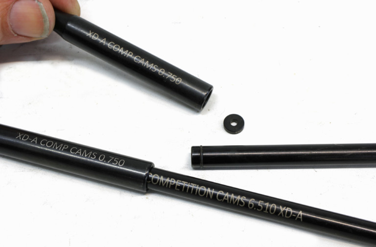
As a final test, we wanted to try Comp’s new XD-A adjustable length, two-piece pushrods. The two-piece design is not only far stiffer than a typical 0.080-inch-wall, 5/16-inch diameter pushrod, but also allows the addition of specially machined spacers that fit inside the lower, larger rod to adjust the length. In our XD-A kit, the lower piece has an effective length of 0.750 inch with the upper at 6.510 inches.
With no spacer, this makes their combined length 7.260 inches. We wanted to run close to the same length as the pushrod we were removing just to see the effect of the stiffer design. We added a 0.116-inch spacer to create a 7.376-inch overall length which was within 0.024 inch of the 5/16-inch 7.400-inch pushrods used in the previous test.
The pushrods were easy to assemble using the included spacer kit. We oiled the small O-ring, installed the spacer in the larger-diameter hollow section, and pushed them together. The larger diameter is used adjacent to the lifter and dropped right into place. If you plan to use these XD-A pushrods in smaller 4.8- or 5.3-liter LS engines with production heads, we’ve seen one or two instances where the pushrod hole in the head may require some clearancing. But that is a minor issue.
The XD-A pushrod design slips the smaller, 5/16-inch portion of the pushrod inside the larger 7/16-inch end, creating an overlapping section that is very strong. Length is adjusted by using varying combinations of calibrated spacers. When installing the XD-A pushrods, the larger section is inserted first into the engine next to the lifter.
The results of our last series of runs proved more than a little interesting. We expected that the stiffer, XD-A two-piece pushrod configuration would reveal its attributes at the top of the RPM curve, but the results revealed the exact opposite. The XD-A pushrods were worth a surprising 12 lb-ft torque improvement at 3,200rpm, yet as the RPM climbed, the benefit diminished, losing three to four horsepower at the peak.
We think that if we had increased the pushrod length by adding a 0.050-inch shim that we could have improved the peak horsepower with no loss of torque at the bottom but unfortunately we ran out of time. Overall, the test was both educational with a sizeable increase in power by merely managing the valvetrain more efficiently.
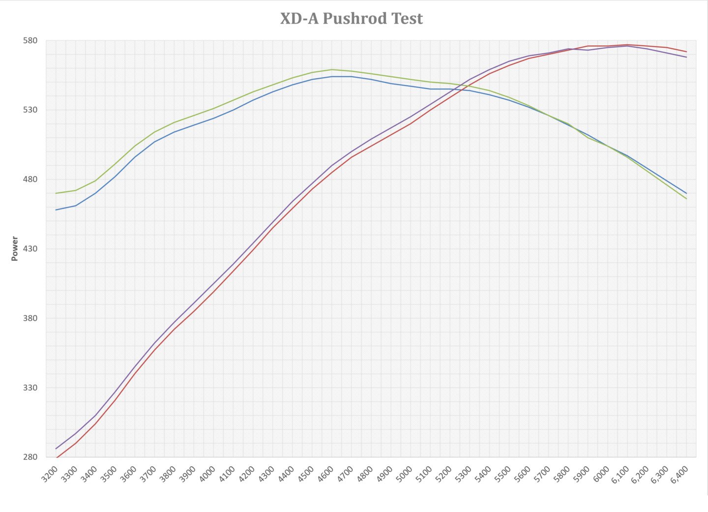
We thought it was interesting that the XD-A pushrods helped bottom end torque much more than we anticipated while losing a couple of horsepower at peak-RPM. This was where we thought the pushrods would show their greatest improvement. If we had lengthened the pushrods by another 0.050-inch, this almost assuredly would have gained power at the top with no loss of torque at the bottom.
For this particular RPM package, it appears that our engine would benefit from using stock rockers and increasing the length of the XD-A pushrods by 0.050 or perhaps 0.075 inch in length. This might add another four to five hp at the peak with no loss of torque down low, creating a much more powerful engine across the entire RPM span.
This new technology is worth investigating more thoroughly. Generally, when adding a camshaft with a longer duration, this results in a significant loss of low-speed torque to gain a small horsepower advantage. In this case, the 0.050-inch duration numbers on the intake side did not change, but with a shorter exhaust duration number, and peak power improved substantially.
This can be attributed solely to managing the valvetrain more efficiently with more measured control over the opening and (most importantly) the closing side of the valve lift curve. This resulted in more horsepower. Of course, this success immediately offers even more power potential if we consider a bigger camshaft.
Now that we’ve shown that the valvetrain is stable, we could easily bump the cam timing up by choosing the Stage 2 LST cam that increases the intake duration by another 6 degrees and adds 0.050 inch of valve lift! That might be worth another 15 horsepower and push our 404ci motor very close to that magical 600-horsepower mark. But clearly, the LST family of cams and upgraded valvetrain has uncovered a way of adding power while also improving valvetrain stability. That’s a win in anybody’s book.
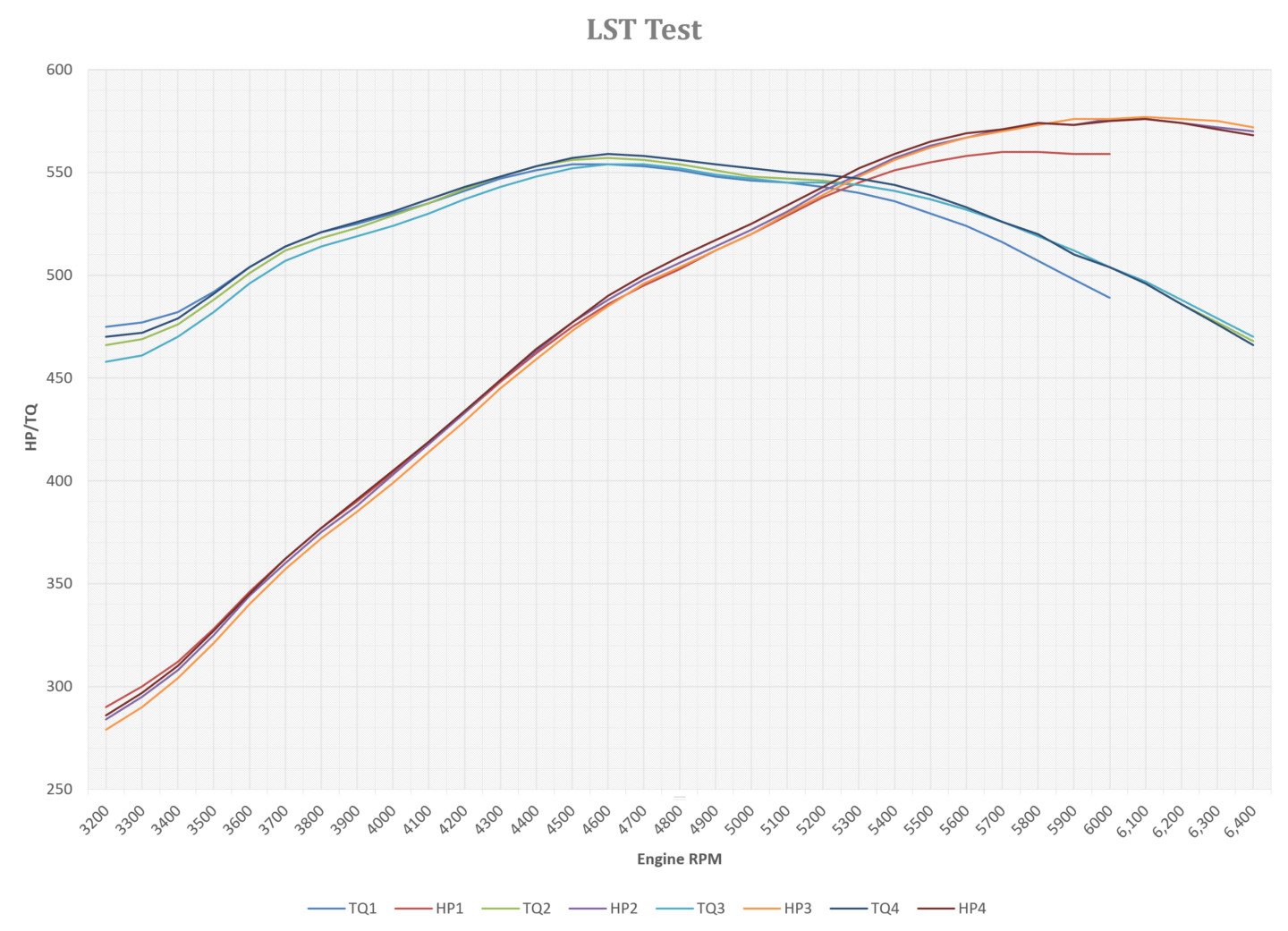
With multiple runs, the overall graph can be somewhat busy, but it’s clear that the LST camshaft, despite the fact that the cam timing figures are very nearly the same, improves power at the top end at the sacrifice of a small amount of torque at the very bottom.
Final Dyno Numbers
| RPM |
Baseline
TQ |
Baseline
HP |
LST Cam
TQ |
LST Cam
HP |
BSR
TQ |
BSR
HP |
XD-A
TQ |
XD-A
HP |
| 3,200 | 475 | 290 | 466 | 284 | 458 | 279 | 470 | 286 |
| 3,400 | 482 | 312 | 476 | 308 | 470 | 304 | 479 | 310 |
| 3,600 | 504 | 346 | 501 | 344 | 496 | 340 | 504 | 345 |
| 3,800 | 521 | 377 | 518 | 375 | 514 | 372 | 521 | 377 |
| 4,000 | 530 | 404 | 529 | 403 | 524 | 399 | 531 | 405 |
| 4,200 | 541 | 433 | 542 | 433 | 537 | 429 | 543 | 434 |
| 4,400 | 551 | 462 | 553 | 463 | 548 | 459 | 553 | 464 |
| 4,600 | 554 | 486 | 557 | 488 | 554 | 485 | 559 | 490 |
| 4,800 | 551 | 503 | 554 | 506 | 552 | 504 | 556 | 509 |
| 5,000 | 546 | 520 | 548 | 522 | 547 | 520 | 552 | 525 |
| 5,200 | 543 | 538 | 546 | 541 | 545 | 539 | 549 | 543 |
| 5,400 | 536 | 551 | 541 | 557 | 541 | 556 | 544 | 559 |
| 5,600 | 524 | 558 | 532 | 567 | 532 | 567 | 533 | 569 |
| 5,800 | 507 | 560 | 520 | 574 | 519 | 573 | 520 | 574 |
| 6,000 | 489 | 559 | 504 | 576 | 504 | 576 | 504 | 575 |
| 6,200 | 486 | 574 | 488 | 576 | 486 | 574 | ||
| 6,400 | 468 | 570 | 470 | 572 | 466 | 568 |


